Share
Pin
Tweet
Send
Share
Send
On the Internet now there are a huge number of different sound amplifiers, for every taste and color, for any need. As you know, even the most reliable amplifiers tend to fail, for example, due to improper operating conditions, overheating, or incorrect connection. In this case, it is likely that a high supply voltage will be at the output of the amplifier, and, therefore, will be unhindered right on the speakers of the speaker system. Thus, a failed amplifier pulls the speaker system connected to it “into another world”, which can cost much more than the amplifier itself. That is why it is highly recommended to connect the amplifier to the speakers through a special board called speaker protection.
Scheme

One of the options for such protection is shown in the diagram above. The protection works as follows: the signal from the amplifier output is fed to the IN input, and the speakers are connected to the OUT output. The minus of the amplifier is connected to the minus of the protection circuit and goes to the speakers directly. In the normal state, when the amplifier is working and relay protection is supplied with power, Rel 1 relay closes the input of the board to the output and the signal goes directly from the amplifier to the speakers. But as soon as a constant voltage of at least 2-3 volts appears at the input, the protection is activated, the relay is disconnected, thereby disconnecting the amplifier from the speakers. The circuit is not critical to the resistor ratings and allows for scatter. The transistor T1 can be set 2N5551, 2N5833, BC547, KT3102 or any other low-power npn transistor. T2 must be composite with a large gain, for example, BDX53 or KT829G. The LED in the diagram serves to indicate the status of the relay. When the relay is on, the signal goes directly from the amplifier to the speakers. In addition to protection against constant voltage, the circuit provides a delay in connecting the speaker system. After applying the supply voltage, the relay does not turn on immediately, but after 2-3 seconds, this is necessary in order to avoid clicks in the columns when the amplifier is turned on. The supply voltage of the circuit is 12 volts. Any relay can be used with a supply voltage of the winding 12 volts and a maximum current through the contacts of at least 10 amperes. A button with a latch S1 is displayed on the wires, it is needed to force the relay to turn off, just in case. If this is not required, you can simply short-circuit the tracks on the circuit board.
shema-zaschity-akusticheskih-sistem.zip 46.57 Kb (downloads: 430)

Device assembly
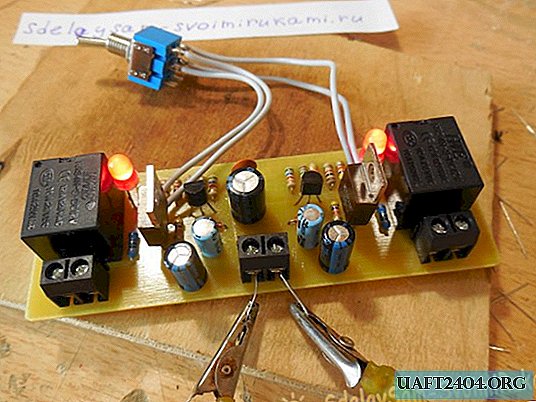
Amplifiers are most often designed for two channels, left and right, so the protection scheme must be repeated twice for each channel. For convenience, the board is divorced so that it already provides for the assembly of two identical circuits at once. The printed circuit board is made by the LUT method, its dimensions are 100 x 35 mm.

After drilling the holes of the track, it is desirable to tin. Now you can begin to solder the parts. Particular attention should be paid to the transistor base, it is very important not to confuse it and solder the transistors with the right side. As usual, first small parts are soldered - resistors, diodes, capacitors, and only then transistors, terminal blocks, and last but not least massive relays. To connect all the wires, you can use the terminal blocks, places for which are provided on the board. After soldering is completed, the flux residues must be washed off the tracks and the installation correct.


Protection tests
Now that the board is completely ready, you can begin testing. We supply power to the circuit (12 volts), after two seconds at the same time the relay should click and the LEDs will turn on. Now we take some source of constant voltage, for example, a battery, and connect it between the minus of the circuit and the input. The relay should turn off immediately. We remove the battery - the relay switches back on. You can connect the battery by changing its polarity, the circuit operates regardless of what polarity the voltage appears at its input. We do the same manipulations with the second circuit located on the same board. The protection threshold is approximately 2 volts. Now that the protection board has been tested, you can connect it to the amplifier and not be afraid that the speakers in expensive speakers will deteriorate due to damage to the amplifier. Successful assembly.


Share
Pin
Tweet
Send
Share
Send

