Share
Pin
Tweet
Send
Share
Send
PSU without a network transformer is easy to do with your own hands. Need some radio components and a soldering iron.
Description of the unit
The transformer circuit is bulky and heavy. To lower the voltage use the property of the capacitor to provide reactance to alternating current. If you use a divider with active resistance, problems arise:
1. With large resistor ratings, the circuit current is small, the potential difference at the output is insufficient to power the device.
2. A decrease in resistance will raise the voltage, but the current through the quenching resistor will increase, it will heat up intensively until it burns out or makes a fire.
At the capacitor, the alternating current and voltage are phase shifted. At the beginning of the charge cycle, the current is large, and the voltage across the capacitor is small and gradually increases. When the capacitance is charged, the voltage increases, and the current decreases to zero. At the same time, they are not big. A small amount of power is released on the capacitor, the case heats up a little.

Mains voltage is supplied to the diode bridge through a capacitor. A divider is formed from the reactance of the capacitance and diodes. A small part of the voltage rectified by the bridge is smoothed by an electrolytic capacitor. Normalized zener diode 12 V power is supplied to the motor. In parallel with the ballast capacitance, a resistor is included that smooths the inrush current when power is applied and provides a capacitor discharge when turned off.
Details
The circuit operates under a network voltage of 220 V, so they use capacitors with an operating voltage of at least 600 V, paper type KGB or film K73-17. The thermal dissipation power of the resistor is 0.25 ÷ 0.5 W.

The minimum permissible reverse voltage of the diodes is 400 V. D226B, KD105B-G or their imported analogues are suitable. Diodes are replaced by the bridge assembly KTs402-407. The zener diode is selected with a maximum current at an operating voltage of 12 V.

The parallel connection of capacitors increases the total capacity by summing the ratings of all elements. The desired value is selected by combining several elements.

Mounting
There are few details, their conclusions are hard. It is possible to assemble a power supply unit by a hinged installation without a printed circuit board, avoiding a short circuit in the connections of the terminals of the parts.

The circuit assembled without installation errors from serviceable parts starts the cooler engine when the power is turned on.

Check the operation parameters will help the multimeter in the mode of measuring DC voltage, connected in parallel with the cooler. The range of operating voltage of the motor is in the range of 9 ÷ 14 volts. At the upper boundaries, the noise of the fan increases markedly. An increase in ballast capacity increases the output voltage. Reduction is the opposite.

Placing the mounting in a plastic case will protect against electric shock. To connect the wires at the input and output of the unit, terminal pairs are installed.

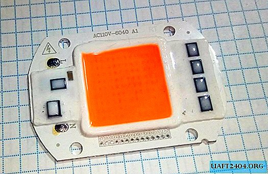
The case is mounted on a radiator with an LED matrix placed on it. The power cord is connected to the parallel connected power leads of the LED driver and PSU.

You need to make sure that nothing interferes with the free rotation of the blades.

Circuit features
All circuit elements are under a life-threatening voltage of 220 V, therefore:
- work with the circuit when the power is off and the ballast capacitor is discharged;
- disconnecting the load (cooler) without first turning off the power will lead to failure of the unit;
- it is necessary to protect the circuit from short circuit by installing a fuse.
The absence of galvanic isolation of the power supply from the network is compensated by the small size, weight and low noise level during operation.
Share
Pin
Tweet
Send
Share
Send


