Share
Pin
Tweet
Send
Share
Send
Required Materials
Before starting the manufacture of the press, you will need to purchase or find in the bins:
- steel square pipe 50x50 mm;
- steel corner 40x40 mm;
- steel strip 40x4 mm;
- steel plate 10 mm;
- steel plate 4 mm;
- 5 t bottle jack;
- 2 coil springs for a trampoline;
- 2 J-shaped bolts with nuts;
- 12 60 mm M10 bolts with nuts;
- 2 M10 x 80 mm bolts with nuts;
- 2 M10 bolts for a hexagon wrench 30 mm long;
- 4 M8 bolts for a 16 mm hex key;
- 2 bolts M10 by 16 mm;
- 4 bolts M6 16 mm;
- 1 x 30 mm M10 bolt for Allen key
- stock with a heel.
The process of manufacturing a hydraulic press from a jack

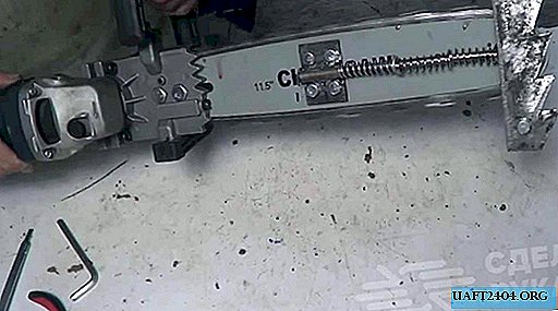
First, cut 2 workpieces from a square pipe. They will be further used as the main rack of the machine. Their length was selected for the parameters of the jack. I got 66 cm. I also immediately make legs from the corner. To ensure their stability, a length of 30 cm is quite enough.

I put on the corner with the help of a core marking for drilling, after which I prepare 2 holes for the M10 bolts. I put the corner in place on a square pipe and equal it at 90 degrees to make markings for drilling. I am preparing a through hole through both walls of the square. Now I connect the pipe and the corner with long bolts and nuts.

After the racks are ready, I cut two pieces from a corner 40 cm long. They will be used as the upper reinforced stop for the jack. I put them one at a time in place and put the markings for drilling. First I make holes in the corners, after which I also drill a square.

I insert 2 M10 bolts on each side. I pull the rack and both corners together.

From the existing thick steel plate, I cut a rectangular workpiece measuring approximately 80 by 13 cm. The piston of the jack will abut against it. Now I turn the rack so that the transverse corners are at the bottom. I put the plate across and drill in its center.


To prevent the ram cylinder from slipping under load, a stop is required. To do this, cut out another plate, but a little smaller. To do this, use a thin plate of 4 mm. I make through holes on it, moving them from a large plate. Also in its center with a milling cutter I choose a large diameter hole, which will include the heel of the piston of the jack. In order not to use nuts, I cut the threads in a thin plate. Now I put both plates to the support from the corners and twist everything with M10 bolts (30 mm long with a head for a hex key).


Now I make a sliding support to secure the bottom of the jack. Serious loads will not be exerted on it, so I decided to make it out of a steel strip.


To begin with, I cut two blanks 16 cm long. I made two transverse marks on them at a distance of 5.4 and 10.8 cm from one of the edges. After I make a wedge-shaped cut with a grinder, but I do not cut to the end. By the resulting groove, I bend the strip, getting a U-shaped profile that easily slides along the machine rack.

Having applied the profile in place to the rack, I measure the distance between them, while taking 4 mm to the tolerance. I transfer dimensions to the steel strip. Its length should be 8 cm longer. I make a mark, having previously stepped back from the edge by 4 cm. After that, I cut the wedge-shaped grooves of the grinder in the same way. I bend the tails obtained at the edges of the strip to 90 degrees.
Now you need to connect the blanks obtained from the strip. To do this, first drill holes on the tails and immediately cut the threads in them so as not to use nuts later. I also prepare holes in the U-shaped profile and connect everything with M8 bolts to the 16 mm hex head.


Next, I take a steel plate with a cross section of 4 mm and put the bottom of the jack on it and draw around it, make tolerances and cut it off. I try on the obtained blank in the center of the lower support made of a steel strip. Make 2 holes, and cut the thread. I connect the plate and the rack, after cutting off the extra length of the bolts.


I make four holes in the bottom of the jack. After that, I put it on the bottom stop plate, mark and drill. I also cut the thread.


In the center of the plate, the jack support makes a through hole. After I partially expand it under the head of the M10 bolt, but I do not drill through, just to drown the hat.


On a steel strip with guide profiles, I retreat a few centimeters from the base plate through the hole. In the future, they are useful for securing the springs.

I begin to assemble the movable part of the machine. First, I screw the M10 bolt into the central hole of the plate using an Allen key. His head is completely hidden. I put the jack on top and fix it with small bolts, also under the hex key. I insert J-shaped bolts into the side holes in the strip. Tighten them with two nuts.


Now, on the upper stop of the machine, opposite the J-shaped bolts, I make transverse through holes through both corners. I insert the bolts and connect them with springs with J hooks.


Again I take a steel corner and cut off 2 pieces of 40 cm each. They will be used as a stand for the location of the pressed workpieces. I’ll check it in the same way that I used when attaching the upper stop of the jack. To add rigidity, I made 2 inserts from segments of a square pipe, also they will not allow the platform to warp and fall when moving.


Now the final stage. I take a steel rod with a heel and cut to the desired length.


I make a hole for the M10 bolt in its end. I cut the thread and screw the rod to the bolt that was previously screwed into the center of the lower stop of the jack.


It remains only to make through holes in the racks in order to be able to change the height of the platform to the necessary parameters of the workpieces. I have only done a couple so far, in the future I will drill if necessary.


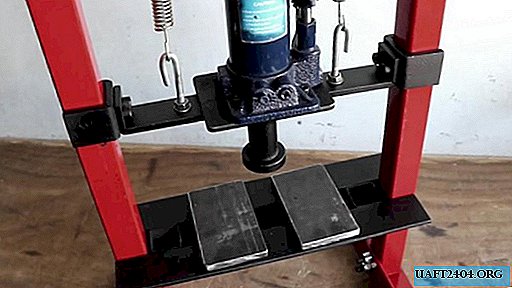
You can start testing. The standard jack handle is not comfortable, so I replaced it with a longer tube.

To protect against corrosion, he painted everything in red and black.

When assembling, I refused to use welding, because it is important to observe the correct angles. When welding, the part can lead to the side. As you know - skew, pressure and welds are incompatible. The main advantage of the design is that, if necessary, I can always remove the jack and put it back.


Watch the video of the manufacturing process
Share
Pin
Tweet
Send
Share
Send