Share
Pin
Tweet
Send
Share
Send
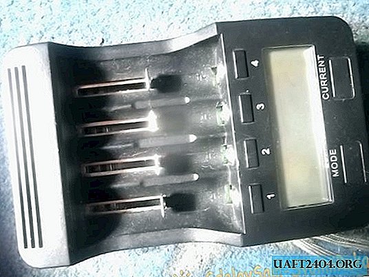
The background that inspired me to finalize it. Somehow I bought myself such a charge, and I liked it, but here the problem she died in a year, I used it without turning it off, and she measured the capacity for this year about 2000 cans of 18650 li-ion. After I tried to repair it, but for more than a week she did not work. Accordingly, I spat on her and bought a new one, and threw the old one into the box by soldering. And in this article, I decided to finish it with a new charge, so that it would not break for a long time.
Modifying the charger
Let's get started!

First of all, untwist the case, the litokaly of screws 6 and they are from the bottom.

Remove the cover from this device.

And what do we see?


I marked red with resistors, which consumes battery power during a discharge, with blue logic, a processor and two other small microcircuits, I still did not understand what kind of microcircuits they were, I marked yellow with a processor power supply.

Let's continue the disassembly. We take out the board.

The board rests on the contacts, so we pull them out. We turn the contacts sideways as shown in the photo. Be careful, do not bend the fastening with the letter g in any case on the contact - since I already broke 1 on the old lithokal which was the first.

Hooray, pulled out!
Now you need to disconnect the connector from the screen.

So we see:

The red ones are the mofetas responsible for the discharge and the blue ones for the charge.
Also on my copy of the memory I noticed a very crooked soldered diode and this is so in the factory.

Let's proceed to the revision itself!

First of all, we cut small radiators, you can put ready-made radiators, but I don’t have them, so I repaired them from a piece of copper transformer of the ATX power supply unit.

We fasten them.

Also do with the second.

This is how it looks with me.

The camera cannot catch the focus. We take a plate of copper, cut it out as in the photo and glue it on second glue.

On charge transistors in the middle.

We also cut and glue on the side transistors of charge 1 and 4 slots

After the glue of the radiators has dried, we begin to collect.

We put the contacts in place sideways and this is much more difficult than removing them.

We cling to the springs.


To do this, we hook the spring with a fingernail and pull down from the first attempt will not work, but it will come out from 6-7.


Now we take a thermal gum.

The mode into pieces and the first thing we put on the resistors, since they are very hot.

We put the rest as here. But this is optional since everything else is heated less.

Now let's collect this device.


Done!

Now check for performance. Everything worked for me on the first try.
Share
Pin
Tweet
Send
Share
Send

